|

| |
Worm Block
Bearing Replacement for Mountain
Instruments 250
If you ONLY need to adjust them
click here.
For
a job/task that I was dreading to do, this went by in a flash. Here is the low
down on just how easy this can be:
CYA WARNING -- You do this procedure solely at
your OWN risk, and YOU assume any/all losses/damages due to this maintenance
procedure failing to work, regardless of whether you properly OR improperly
followed the following procedure. You decide if this is right for you.
Disassembly:
- The Oldham
coupler on the worm side has "Green Loktite" on it and must be pried
off of the worm shaft. I used a large flathead screwdriver in a
twisting motion while constantly rotating the worm shaft. Yes, I did
leave some minor scratches/indentations on the aluminum block, but this is
what it takes to remove such a Loktited part. I had removed the
set-screws earlier. Once the Oldham is removed, you must scrape off
the remaining Loktite from the worm shaft in order to slide/remove the shaft
from the worm bearing (part # SS698ZZ from American Bearing Works) after you
take the worm block assembly apart.
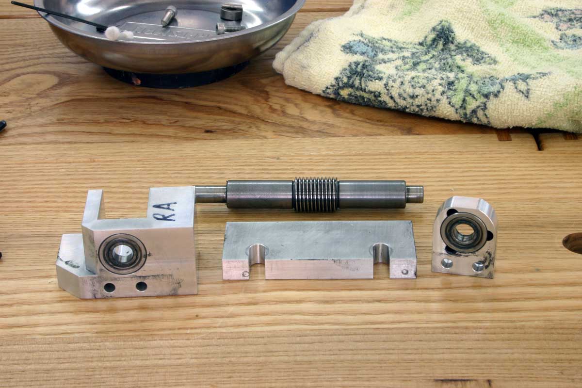
- Worm block is
made of THREE blocks of CNC'd aluminum bolted together with 3/16"-32 screws.
- The two motor
side screws are LONGER than the adjuster side/end screws. Just
remember this when reassembling.
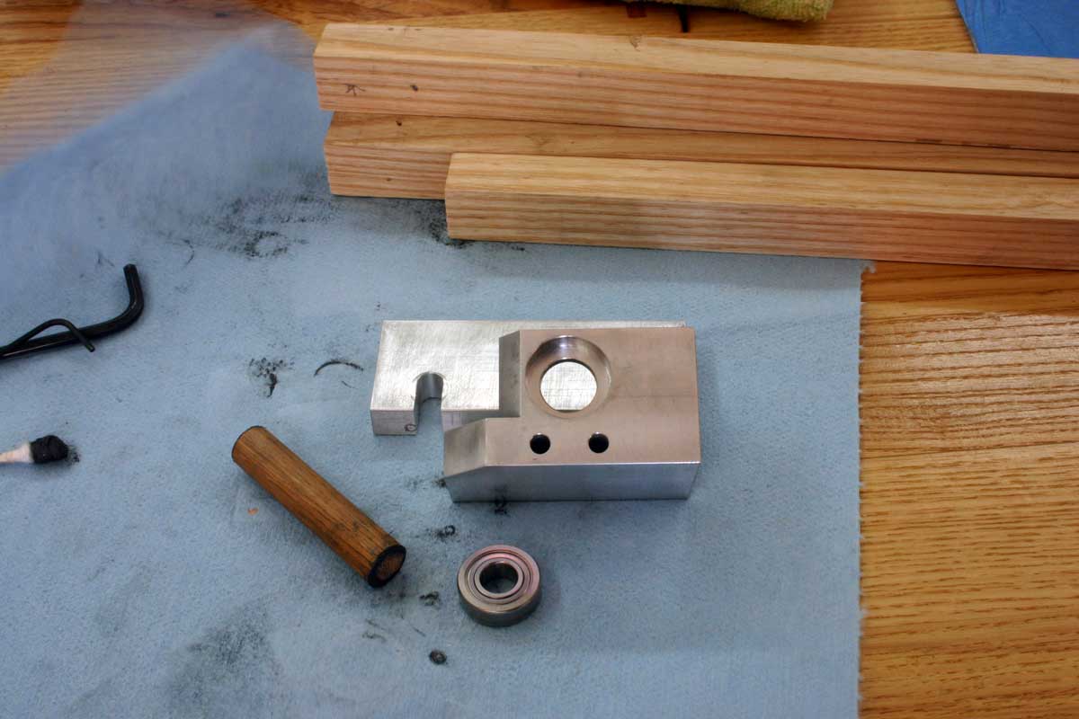
- The second image
shows my 1/2" wooden dowel tool that I used to drive out the bearings using
a dead-blow hammer. The motor side bearing was quite tight, possibly
got some of the "Green Loktite" that migrated along the shaft and
cured. Remember that "Green Loktite" is for preassembled parts,
SO BE VERY CAREFUL AND FRUGAL when reapplying it to the Oldham coupler.
Reassembly:
- Before attempting
to press the NEW bearings into place, I rubbed a VERY LIGHT coat of Jet Lube
MP-50 on both the recessed area as well as the outer bearing race. I
mean that you could barely see that I had applied any at all. Remember
that MP-50 will leave a thin film/coating even after wiping off.
- Lacking a PRESS,
I placed the bearing flat on my solid flat workbench, aligned the
appropriate block end directly over the bearing and attempt to first press
by hand to get it started and then tapped with a dead blow hammer to
completely seat the bearing. CHECK FREQUENTLY to see that the bearing
is driving square to the block and tap on opposite sides to correct while
driving it home.
- FWIW, I found the
motor sides tight and the adjuster side bearing a much looser fit.
IMPORTANT: Be sure to back out the worm "adjuster screws" before
installing the bearings.
- After the
bearings are in place, it is time to re-assemble the entire worm block.
Remember the SHORT screws go to the adjuster side and the LONG screws go to
the motor side of the worm block.
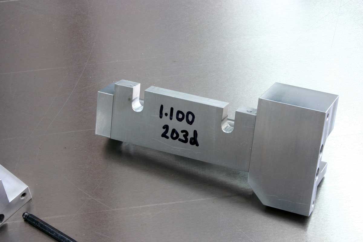
- Once all of the
screws are loosely in place, and you remembered to insert the worm before
putting the block together ;-), place the entire worm block assembly
on the FLATTEST reference you have. I used my tablesaw. Now.
while holding the three loosely held together block parts, tighten the screws.
This will make sure the block is square to itself and will sit on the
reference block that is attached to the RA and DEC housing. Remember
to put all those brass shims back in the same exact order you took them
apart.
- A note on
tightening screws -- Do NOT get carried away tightening. Give them a
good tight snug, but DO NOT torque them. You will only create problems
for yourself if you do.
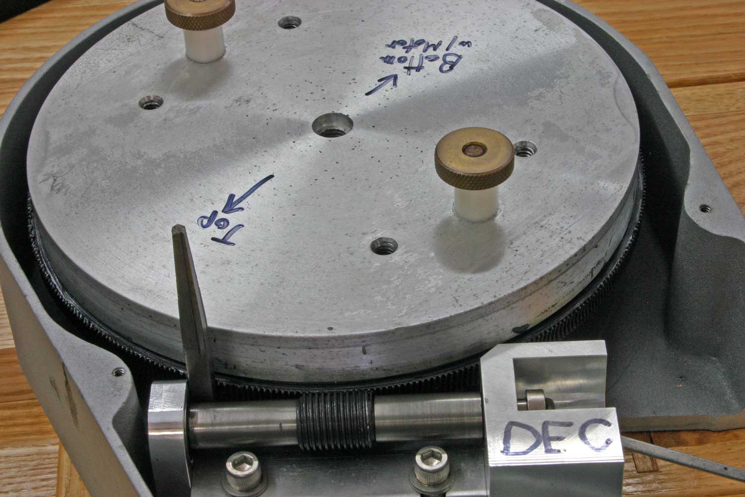
(below) When
reinstalling the worm block(s) to their respective worm gears, I used a
screwdriver in the Oldham coupler to drive the worm gear around. Before
you do this make sure your clutch bolts are snug-tight to the gear. This
takes longer to do, however, using a screwdriver to turn the worm this way
allows me to get a feel of just how tight/loose the worm meshing is at all
times. When I get to a tight spot (really usually just one per worm gear),
I mark it with a Sharpie "dot" and make several adjustments until the meshing
feels snug but still easy to turn the worm/Oldham. Notice the
1/4"key-stock" placed on the left side of the worm. As Larry Meyers told
me, that once the worm meshing is correctly set, that key-stock should just
barely fit/slip in and out of this position. This assures that the worm is
properly square with the gear. Do remember to put all those brass shims
under the worm block back exactly as you took them out. Anyway, I made at
least two revolutions of the main gear and reworked the tight spot before I put
the cover back on the RA axis and put it back on the pier in the observatory.
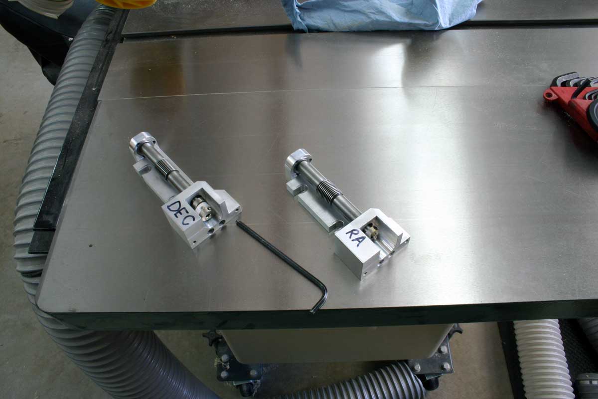
FUN TIME -
After mounting the RA back on the pier, I returned to my garage/shop to do the
DEC axis the same way, only to discover that I had used the DEC shims in the RA
assembly! So out to the observatory I went and removed and re-did
the entire meshing routine after I got the CORRECT shims in place this time.
I had labeled both the RA and DEC separately and kept them in individual bins,
but that never stops one from making these kinds of mistakes. Double and
triple checking your own work is NEVER a bad thing to do. You never know
when that old pig farmer might jump up and get you! You know who I'm
talking about,... Al Swiners...of course!
Additional "Learned-from-doing" Tips:
- After
reassembling and adjusting the worm play out of the worm block, I got to
thinking. Even though I had "seated" the motor-side bearing flush with
that end's block recess, I was not sure that that was enough. So I
up-ended the assembled worm block motor-side down, took my dowel rod tool
and dead-blow hammer and tapped the end of the worm shaft down against the
"seated" bearing. Guess what... the bearing was NOT completely
seated after all. I now had visible back and forth "play". I
could move the worm shaft sideways by hand that now needed adjusting out.
I then readjusted the worm play and all is NOW finally fine and dandy.
BTW, I had to do this with both the RA and DEC worm blocks. LESSON
LEARNED -- Basically, if I had not discovered this then the first time my
mounting was out of balance, the worm shaft would have slipped sideways and
shown up as large PE.
-
|
